Previous article
37% Of Design Is Choosing Components?
Octopart Staff
All electronics projects need power. Power can come from either stored energy in a battery, or directly from mains AC voltage or DC power from renewable sources such as solar energy. Power Management ICs (PMICs) help manage the power requirements in a system including scaling voltages, battery charging, and DC-DC conversion. Choosing the right PMIC can make a difference in whether the final product becomes successful or not. An integral part of any PMIC solution is a voltage regulator. Voltage regulators provide a constant output voltage from a higher or lower input voltage. In this blog, let’s look at the variety of voltage regulators, how to choose them, and how Octopart data can help you make the decision to choose the right voltage regulator for your project. This is a follow-up on our series of blogs on how to select a capacitor, resistor, inductor, connector, IC packages and MCUs.
Voltage regulators provide a stable DC voltage during operation of a system. Voltage regulators can receive power from either mains AC voltage from wall outlets or from batteries in electronic devices. Batteries discharge almost linearly with time and voltage regulators are needed to maintain stable power supply for electronic systems. This can be seen below:
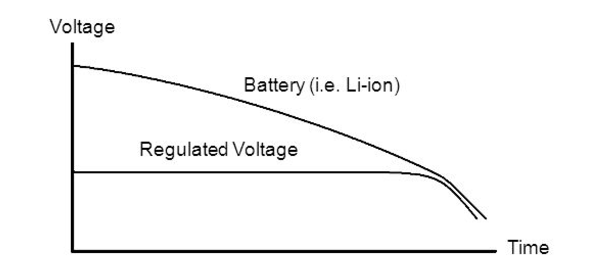
Batteries discharge with time -- voltage regulation is required
In addition to powering circuits, a precise DC voltage is often used as a reference to which voltage signals are compared to make decisions. If this reference voltage is not very stable and fluctuates a lot, it affects the decision making of a system. NOTE: Input voltage and supply voltage are sometimes used interchangeably, as voltage regulators use supply voltage as their input.
Let’s dive into some of the most common parameters that are used to choose a voltage regulator. We’ll take Texas Instruments’ TPS76733 as an example to learn about the parameters that drive the decision to choose a particular regulator.
IMPORTANT PARAMETERS:
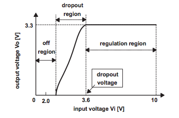 Dropout region of a 3.3V voltage regulator
 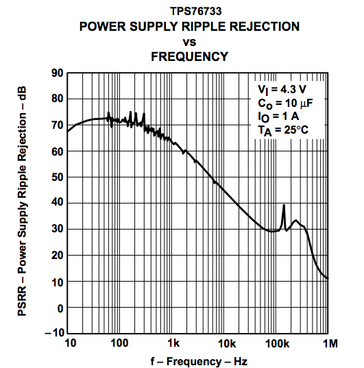 Higher frequency supply ripple impacts output more due to lower PSRR
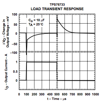 Output voltage showing spikes of 100mV when load current switches
 Get more info by reading this excellent manual on the parameters above.
TYPES
There are two main types of voltage regulators. The first type is linear voltage regulators. Linear voltage regulators step down the voltage using impedance control at the output. The second type is switching voltage regulators or DC-DC converters. Switching voltage regulators can step up or step down the voltage depending on architecture and they achieve so by using on/off switching operations. Linear regulators are usually less efficient but cheaper, on the other hand, switching regulators are more efficient but are much more expensive.
Linear voltage regulators are used to step down a high input voltage to a steady voltage at the output. Linear regulators achieve this by changing the impedance at the output according to load current, resulting in constant output voltage. A typical linear voltage regulator is shown below. When the dropout voltage is low, it is called a low dropout regulator or LDO. LDOs have PMOS or PNP BJT as their Pass FET. Cout is a minimum capacitor at the output pin to ensure stability.
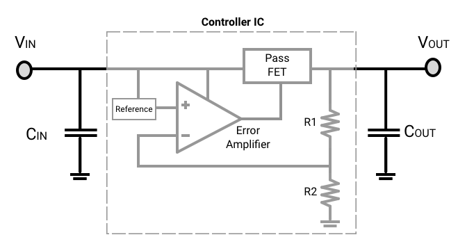
Inside the IC of a linear voltage regulator
Part Selection: Surface Mount: STMicroelectronics’ LD1117 series [CPL] Texas Instrument’s LP2985 series [CPL] Through-Hole: ON Semiconductor’s LM317 series [CPL]
Switching regulators or DC-DC converters are used universally in almost all electronic devices. They are popular as they have high efficiency during both step up (boost converter) and step down (buck converter) of DC voltage. Below is a simplified diagram of a buck converter which is used to step down DC voltage. A controller IC is required to sense the feedback voltage and adjust the switching PWM accordingly. Some DC-DC converters today replace the diode with a transistor for synchronous rectification for higher efficiency. This efficiency comes at a higher cost as a more complex driver is needed.
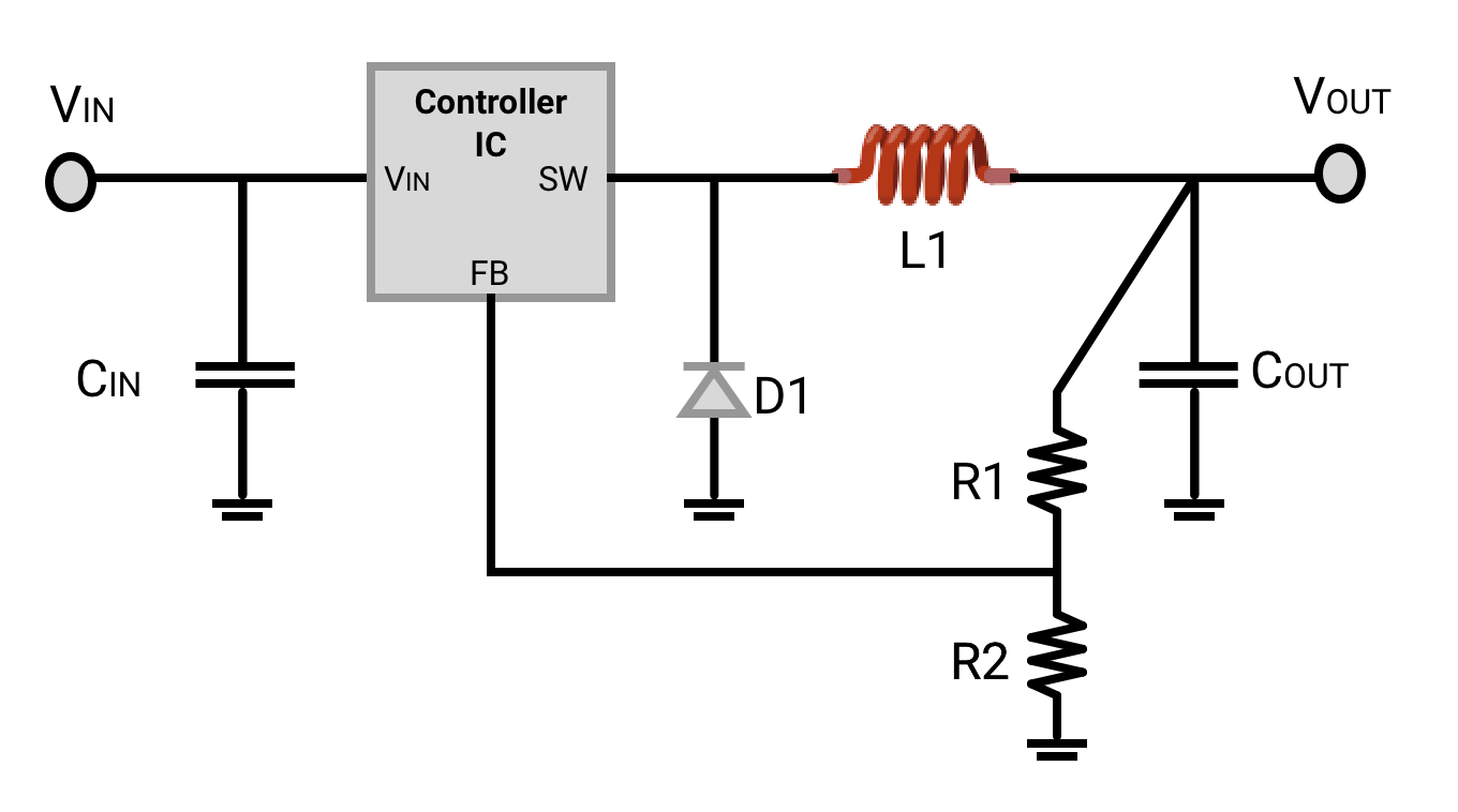
Schematic of a buck converter
You might see these two terms used in the context of switching regulators. Switching regulator ICs handle switching operations within the IC. As a result, they can’t handle a lot of current. With switching controllers, on the other hand, the switching function is done external to the IC which allows for much higher currents. Switching controllers have a lot more options for configuration, and are much more complex than switching regulators. In summary, if you need very high currents, use switching controllers as they use external switching FETs.
Part Selection:
Buck Converter: Texas Instruments’ LMR12010 series [CPL]
Boost Converter: Texas Instruments’ TLV6122 series
This guide covers some of the most popular types of voltage regulators including selecting them for different applications and the important parameters. If you have any comments or suggestions on the part selection, drop us a note in our Slack chat room or in comments below. Till next time.