Previous article
All New Octopart Categories!
Octopart Staff
Electronic components provide definable functions; they are the building blocks of design, and electronic design is all about putting those blocks together in the right way. However, unlike conventional building blocks that fit together with regularity, every electronic component is different. Part of the challenge for engineers is matching the component’s function to the design objective – and it’s not always a simple process.
In order to understand the functions, capabilities and limitations of a component, engineers use datasheets. These don’t simply provide the information (data) an engineer needs to select or reject a component – they are also an integral part of the design process.
Datasheets are technical reference documents, so they won’t contain time-sensitive or commercial information such as unit price or availability, but they will provide engineers with the information they need to compare and contrast different products that offer similar functionality. Parameters may vary between alternatives, such as operating temperature, package options or amount of integrated memory; these are just some examples of how engineers use the design-critical information provided.
One of the most useful features a datasheet provides is pin definitions, normally in the form of a table which will include each pin’s location on the device, and its function. Design notes may also be included - for example, an output may be open drain, in which case it would need a pull-up resistor on its output. This information would only be available in the datasheet and if this requirement isn’t observed during design it would likely result in a fault.
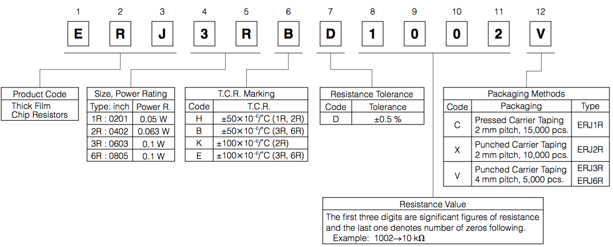
Figure 1(a): The part numbering system for thick-film resistors from Panasonic
While a pin’s function will be consistent across different package outlines, its position will likely change. A datasheet will document these variations and show how they are defined by the part number. Most components are supplied in a range of package options as well as temperature grades, or (for programmable devices) memory sizes - parameters that are reflected in the part number. Understanding how a part number is formed, therefore, allows engineers to define the right part for their application. This is true for all components from discrete passives to integrated circuits. For example, Figure 1(a) shows a part numbering system for thick-film chip resistors from Panasonic, while Figure1(b) shows the part numbering system for the EFR32 microcontrollers from Silicon Labs. For more information about understanding IC packages, checkout the Octopart Guide to IC Packages.
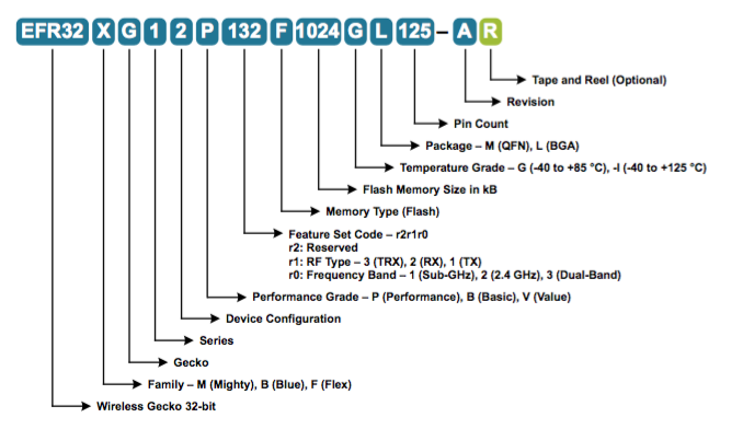
Figure 1(b): The part number system for the EFR32 family of microcontrollers from Silicon Labs
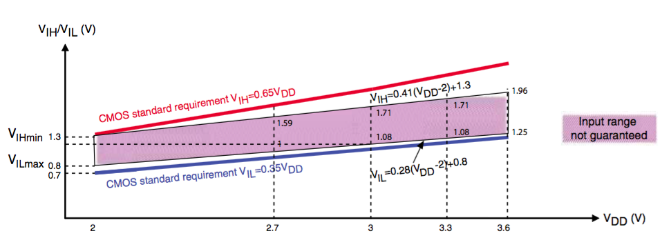
Figure 2: An example of the standard input characteristics for a CMOS port on a microcontroller, as shown in a datasheet
For example, Figure 2 shows the standard input characteristics for a CMOS port on a microcontroller manufactured by STMicroelectronics. It clearly shows how the minimum-logic high voltages and maximum-logic low voltages vary over supply voltage, and includes the operating areas within which the manufacturer cannot guarantee correct operation. This is the kind of operating characteristic that engineers must observe during design, or they risk introducing a design fault that could cause project delays. This information can only be found in a datasheet.
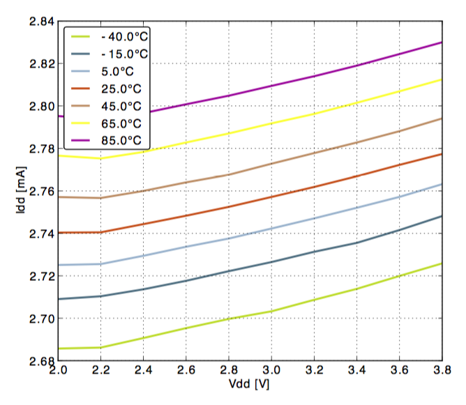
Figure 3: Example of how the active current consumption for a microcontroller is detailed in a datasheet
Understanding the electrical characteristics of individual components is essential at a system level. Figure 3 shows the current consumption for a microcontroller from Silicon Labs, clearly displaying how the supply current (Idd) increases with both operating temperature and supply voltage (Vdd). An engineer would use this information to work out how much current the device would require in the application, by referencing the relevant supply voltage curve at the typical operating temperature. This information would be used when designing the system power supply but can also help engineering teams work out if forced air cooling is required in the application. Of course, every component’s datasheet will be different in this respect but the information will always be provided and presented in the same way - in a table of maximum/minimum parameters and as transfer curves.
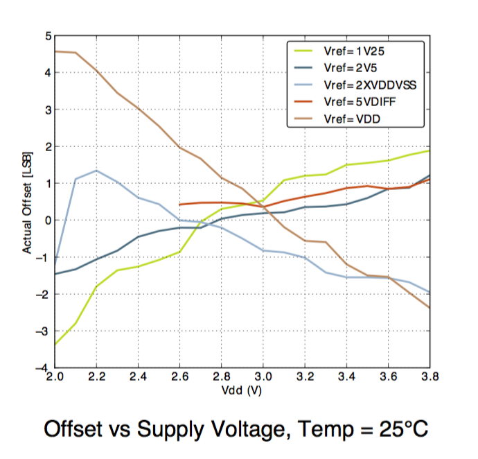
Figure 4: Example of how a datasheet documents the characteristics of a peripheral
Electrical characteristics will also be given for specific features of a device. Figure 4 shows how the output of the analog-to-digital converter (ADC) on the same microcontroller from Silicon Labs varies with supply voltage for given reference voltages. This information is critical in design, as it allows engineers to make provision (perhaps in software) for known possible variations (in this case it is in the Least Significant Bit of the digital output). Note that information provided as transfer curves in this form are normally specified as ‘typical’ and is not intended to be guaranteed; often the data is further classified as only being representative at a given operating temperature (in this case, 25°C).
A programmer’s guide complements a datasheet by focusing on how the SoC is configured. Often this will include information that, unlike a datasheet, extends beyond the device itself, to include the software ecosystem that supports the device, including open source software (and where to find it) and the development environments that support the device. Increasingly, this will include partners who may provide an operating system or middleware, for example. A programmer’s guide has greater scope than a datasheet and is subject to more frequent changes. As such, some manufacturers now choose to publish them as wikis instead of ‘static’ documents, such as the CC3200 programmer’s guide from Texas Instruments.
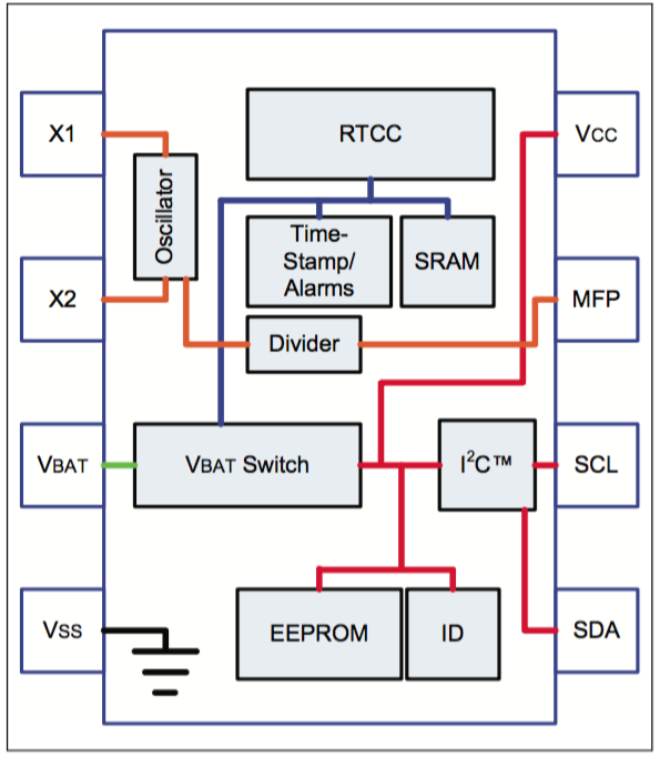
Figure 5(a): Datasheets will normally include a functional block diagram for the parts they cover, as show here for a Real-Time Clock/Calendar (RTCC) manufactured by Microchip
In most cases a datasheet will strive to cover every aspect of a device and how it is used. As an example, the block diagram in Figure 5(a) is for a real-time clock/calendar from Microchip, which represents how the device’s functions are accessed. Figure 5(b) shows how the same device might be used in a circuit. This information is provided in the device’s datasheet, and while it may also be available in an application note, not all manufacturers provide one.
The information provided in a datasheet will be relevant to using the device but it may not go into great detail about how its functionality is achieved. This is particularly true if the function provided is formalized under a recognised standard. An example may be a USB port; an integrated device may offer USB functionality, but the datasheet is unlikely to explain in detail how USB works. In this respect, engineers cannot substitute experience or knowledge for the information found in a datasheet; moreover it is a reference to knowledge an engineer may need in order to use a particular component.
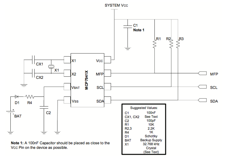
Figure 5(b): Datasheets will often provide examples of how a device should be designed in, as shown in this extract from a datasheet for the RTCC from Microchip
In some cases, a device will provide access to functionality as a ‘black box’, which is particularly true for a device designed to work ‘out of the box’. In this case, the datasheet will still be essential, as it will explain how to access that functionality without the engineer needing to understand how it works. This is increasingly the case with highly integrated SoCs which may provide functions such as bluetooth connectivity, for example.
A datasheet is often the first piece of information an engineer will search for when considering a component, so it’s no surprise that references to datasheets are now appearing in more places. Online access to datasheets is seen as an inflection point in design; it gives more people from different backgrounds the opportunity to explore and get involved with electronic engineering.
The information it contains may not be available from any other source, making it practically impossible to use a component without referring to its datasheet. As such, every engineer working on a design project should have access to the datasheet for every component in that project. Today that may take the form of a digital library on a shared server, rather than a binder full of printed sheets.
Although it’s true to say datasheets have changed little over the years, they have evolved. The datasheet remains as essential as a circuit diagram, bill of materials or code listing. In fact, designing a circuit without the datasheets for each component would be incredibly difficult.