Previous article
Company Tools update
Octopart Staff
When I was working on the the latest version of the Common Parts Library, I realized that it would be helpful to explain why you might pick one type of inductor over another. We started off this series by writing “How to select a capacitor,” followed by “How to select a resistor,” and are continuing with a close look at inductors.
In this blog, we will explain all the different types of inductors, their merits and demerits, and their popular applications. We have included some recommendations for commonly used inductor series with high supply chain availability from the new Common Parts Library, which includes parts from the Shenzhen supply chain via Seeed Studio’s Open Parts Library.
Let’s dive into the world of inductors:


Inductors are two-terminal components used for filtering, timing and power electronics applications. They store energy in the form of magnetic fields as long as a current is flowing. Inductors oppose a change in current by inducing an electromotive force (or e.m.f) according to Lenz’s Law. The inductor can be approximated as an open circuit for AC signals and as a short circuit for DC signals. The unit of inductance is Henry (H) . There are four main factors that affect the amount of inductance of an inductor: the number of turns in the coil, coil area, coil length and core material. When inductors have a magnetic core made up of a ferromagnetic material it results in higher inductance. However, inductors with a magnetic core have losses such as hysteresis and eddy currents. There are several parameters that are important to keep in mind while selecting an inductor:
Recently, Octopart updated search pages to make it easy to filter searches by these parameters, so you can see the best parts that match your search and keep the attributes above in mind. Here’s an example.
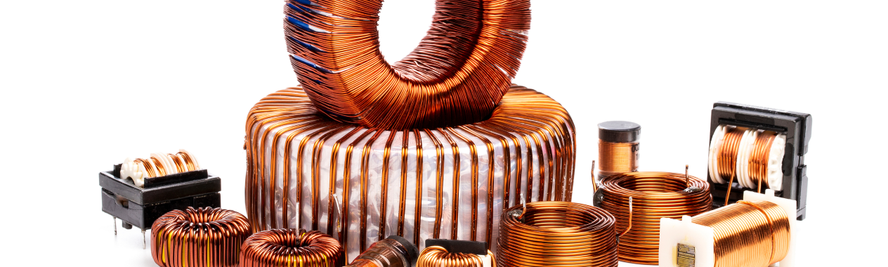
An inductor is also referred to as coil or reactor. If an inductor is used for blocking or decoupling higher frequencies, it is called as “choke”. There are different types of inductors based on materials used in cores and construction. Let’s look at some of the main ones below:

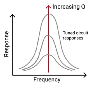
Air-core inductors do not have a core, and their biggest advantage is they have a high Q factor and low losses. As they do not have a core, a larger number of coils are required to gain the same value of inductance which results in increase of size. They are mainly used in high frequency applications such as resonant circuits where low inductance values are sufficient. Part Selection: Wurth Elektronik’s 74491 series for 1.65nH to 120nH

Ferrite core inductors are made of a ferromagnetic material which has high permeability. These inductors have much higher inductances compared to other types. They also have low losses. They are used in noise filters, high quality transformers and DC-DC converters. Part Selection: Bourns’ CM322522 series for 220nH to 100µH [CPL]

Iron core inductors can have very high inductance values due to their iron core. They can handle high power but are limited in high frequency capacity. They are used mostly in low frequency applications such as audio equipment. Fine particles of iron powder are used in iron powder inductors which have higher saturation currents than ferrite core inductors. They are commonly used as radio frequency chokes. Part Selection: Bourns’ SRP7030 series for 100nH to 8.2H

When inductors are wound around a ring or circular toroid, they are referred to as toroidal inductors. Since the toroid has a closed-loop core, it has higher inductance and Q factor than an inductor with straight core (solenoid). Because of the symmetry, the magnetic flux leakage is very low. This structure makes toroidal inductors a good choice for large current and high inductance applications. These inductors are used in DC-DC switching voltage regulators, medical and refrigeration equipment, telecommunication circuits and more. Part Selection: Pulse’s P/PE series for 10µH to 1.5mH
Bobbin based inductors are wound on a cylindrical bobbin and can be either axial leaded or radial leaded. These are mostly used for printed circuit boards (PCBs). They vary widely in terms of power rating, operating frequencies, size and other parameters. Part Selection: Bourns’ 78F series for 1µH to 1mH
These inductors are formed by layering ceramic materials to create an integrated monolithic inductor. They are smaller and less expensive than toroidal inductors. While they have lower Q factor than toroidal inductors do, they provide a good overall balance between tolerance, rated current, size and price. They are used to suppress high frequency noise, RF matching in modules such as wireless LANs and in mobile communication systems. Part Selection: 0402 Murata’s LQG15H series for 1nH to 270nH [CPL] 0603 Murata’s LQG18H series for 1.2nH to 270nH
Film inductors use a film of conductor on their base material which enables them to have an ultra-miniature size. Multiple spiral-shaped thin film coils are created on the substrate which results in compact and highly precise inductors. Compared to multi-layer ceramic inductors, they have low variation. However, film inductors are limited in their maximum value. Their applications are in RF matching circuits that need small inductor sizes and also low tolerance in inductance along with high Q factor. They are also used in DC-DC converters. Part Selection: 0402 Murata’s LQP15MN series for 1nH to 33nH [CPL] 0603 Murata’s LQP18MN series for 1.3nH to 100nH
Ferrite Beads are passive components that remove high frequency electromagnetic interference (EMI) noise from a circuit. Ferrite beads are placed in series with the signal source. Any current that flows through the ferrite bead will create a voltage drop proportional to the DC resistance of the ferrite bead. Hence, it is preferred to have low values of DC resistance. However, it is desirable to have high impedance over some defined frequency range to suppress the noise. Part Selection: 0603 Murata’s BLM18AG series for 120Ω to 1kΩ (impedance at 100MHz) rated at 0.5A [CPL] 0805 Murata’s BLM21P series for 22Ω to 330Ω (impedance at 100MHz) rated at 1.5A [CPL]
The two main applications of inductors are in areas of power electronics and RF circuits. Inductors are an essential component in a variety of DC-DC converters as well as in RF circuits in LC-tuned oscillators. Let’s look at these two applications below:
DC-DC converters or switching regulators are used universally in almost all electronic devices. They are popular as they have high efficiency during step up (boost converter) and step down (buck converter) of DC voltage. Below is a simplified diagram of a buck converter which is used to step down DC voltage. A controller IC is required to sense the feedback voltage and adjust the switching PWM accordingly. Some DC-DC converters today replace the diode with a transistor for synchronous rectification.
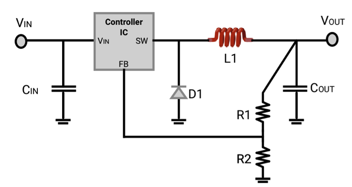
Fig.1 Schematic of a buck converter
To choose the value of the inductor, various parameters, such as input voltage range, output voltage, maximum output ripple, maximum load current, size and the ESR of output capacitors, need to be considered. An inductor should have a high value of rated current so that it can operate in linear range over the entire load. Also, it should have low DC resistance to minimize losses and increase the efficiency of the regulator. It should also have a small size which is important for printed circuit boards (PCBs). Read this guide on designing a synchronous buck converter, and a guide to select inductors for switching regulators as well as this guide titled `Buck-converter design demystified’ to go deeper into inductor selection for DC-DC converters.
Inductors are used in various RF circuits including filters, oscillators and more. Let’s take the example of a Colpitts Oscillator, which is an LC resonance circuit connected between the collector and base of a single stage transistor amplifier. The amplifier is necessary because an LC circuit by itself produces a damped oscillation due to the parasitic resistances of the components. The amplifier in the Colpitts Oscillator ensures undamped oscillations. To select the RF choke, choose an inductor whose self resonant frequency (SRF) is near the frequency where choking is needed. This is because the impedance of an inductor is maximum at its SRF. For an LC circuit, choose the inductor such that its SRF is much higher (~10x) than the operating frequency. The tolerance of the inductor must also be considered as it might lead to unwanted shift in frequency selection. Read this guide on selecting inductors for RF applications to learn more.
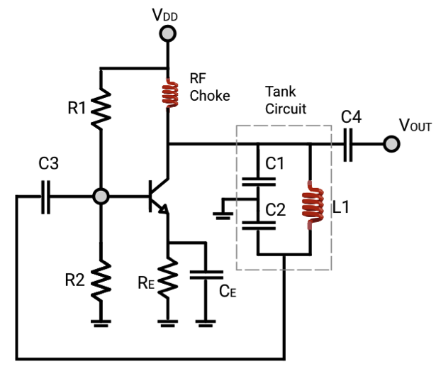
Fig.2 Schematic of a Colpitts Oscillator
This guide covers some of the most popular types of inductors including selecting them for different applications. If you have any comments or suggestions on the part selection, drop us a note in our Slack chat room or in comments below. A guide on how to select connectors is coming soon. Stay tuned!