Previous article
Mouser, Users, TechCrunch, Bryan
Octopart Staff
(Guest blog by Max Scherzer, ATLAS Pixel Detector.)
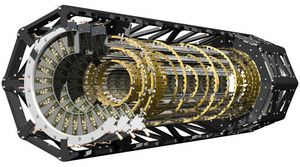
Like many particle physics experiments, ATLAS is a collection of several concentric cylinders, each cylinder being a different detector technology. At the center of all the cylinders two very high energy beams of protons are brought into collision; it's then the job of the different detectors to give some clue as to what just happened by measuring the trajectories of the particles that were produced. The inner cylinders can make very precise measurements of where a particle crosses it, but are also very expensive to build per unit area. The outer cylinders are cheaper per unit area to build, but not as precise. The pixel detector - what I work on - is the inner most layer. It's taken many hundreds of man years to get to where we are now, and all for an active area of less than 1 1/2 square meters. But the upshot is that it will be able to measure track vertices - meaning where the different particles were produced - with an accuracy of a hundred microns, or about the width of a human hair. And it can do that for thousands of tracks every 40 million times a second, all the while operating in an intense radiation field for years.
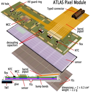
Here's how it works: each module (about size of a booklet of postage stamps; see the diagram) starts from a 15mm by 60mm piece of very high purity silicon. The silicon is divided into a grid of 48,000 little rectangles, each rectangle containing, among other things, a p/n junction diode. Then 16 integrated circuits are laid down underneath the sensor silicon. These ICs amplify and digitize the charge pulses that get created when a charged particle passes through one of the sensor diodes. Then, a 2nd type of integrated circuit - the MCC, for module control chip
The final detector is made up of almost 2000 modules, arranged on a graphite frame. Then the tricky part of snaking the low voltage cables, high voltage cables and cooling fluid pipes through the outer cylinders begins! And of course, this is to say nothing of how one actually makes sense of the data once it's on disk.
So where are we now? The final module design has been finalized for several years and the manufacturing and testing of the modules has been completed for almost a year. In that time, the modules have been loaded onto their mechanical frame and permanently connected to the first series of patch panels that provide service support for the system. In December, an attempt to run 10% of the system simultaneously was successfully completed. Final tests of the connections to the patch panels mentioned above were just completed about 1 week ago; the current plan is to lower and insert the detector inside the other layers before the end of this month. After that, it's still a lengthy road, but we hope to have the entire detector cabled and ready to read-out (still uncalibrated) by the end of year.
working on cool hardware? submit blogs to contact@octopart.com